
next gen ranger aux switches wiring diagram pdf
The Next Gen Ranger AUX switches wiring diagram provides a comprehensive guide for understanding and customizing the electrical system. It includes six pre-wired switches, making it easy to connect accessories and control aftermarket components. This diagram simplifies the process of identifying circuits, wire colors, and connections, ensuring a seamless DIY experience for truck enthusiasts. Perfect for upgrades, it offers a user-friendly layout to enhance functionality and customization.
Importance of Wiring Diagrams for Customization
Wiring diagrams are essential for customizing the Next Gen Ranger’s auxiliary switch system, as they provide a clear visual representation of the electrical circuits. These diagrams help users understand how components connect, ensuring safe and efficient installations. By referencing the wiring diagram, enthusiasts can avoid costly mistakes and ensure compatibility when adding aftermarket accessories. The detailed layout of circuits, wire colors, and fuse locations simplifies the process of upgrading or troubleshooting. Whether installing LED lights, winches, or other accessories, the diagram acts as a roadmap, guiding users through complex electrical systems. This resource is invaluable for maintaining functionality and achieving desired customizations without compromising the vehicle’s electrical integrity.

Key Features of the Next Gen Ranger AUX Switch System
The Next Gen Ranger AUX switch system stands out with its six pre-wired switches, offering seamless integration for aftermarket accessories. These switches are strategically mounted on the instrument panel, providing easy access and control. Each switch operates independently, with circuits individually fused to prevent overloading. The system supports a wide range of customization options, from lighting upgrades to winch installations. Enhanced reliability is achieved through high-quality components and precise wiring configurations. Additionally, the system’s modular design allows for future expansions, making it adaptable to evolving needs. This user-friendly setup ensures that enthusiasts can maximize their truck’s potential with minimal effort, while maintaining electrical system integrity and performance.

Understanding the Auxiliary Switch System
The auxiliary switch system in the Next Gen Ranger is designed for seamless integration of aftermarket accessories, offering six pre-wired switches for enhanced customization and control.
Standard vs. Optional Auxiliary Switch Equipment
The Next Gen Ranger offers standard auxiliary switches, including six pre-wired options for easy aftermarket accessory integration. These switches are mounted in the instrument panel and operate when the ignition is on, providing a reliable power supply for various upgrades. Optional equipment includes additional wiring studs at the battery and under the hood, allowing for further customization. The standard setup is ideal for basic modifications, while optional components cater to more complex installations. Understanding the difference helps users choose the right configuration for their needs, ensuring a clean and efficient setup. This setup enhances functionality while maintaining the vehicle’s electrical integrity.
Functionality and Limitations of AUX Switches
The Next Gen Ranger AUX switches provide six individually fused circuits, enabling users to control aftermarket accessories like lights, winches, or air compressors. Each switch operates when the ignition is in the “on” position, ensuring power delivery only when needed. However, these switches have limitations, such as no functionality when the ignition is off. Additionally, each circuit has a maximum power rating, and exceeding this can cause overheating or damage. Proper wiring and fuse sizing are essential to avoid electrical issues. While highly customizable, the system lacks advanced features like programmable logic without additional hardware. Understanding these boundaries helps users optimize their setup for reliability and performance.
Wiring Diagram Specifics
The Next Gen Ranger AUX switches wiring diagram offers a detailed visual guide, showcasing connections between switches, relays, and accessories. It includes wire color coding, sizes, and circuit paths, ensuring clarity for installations and troubleshooting. This diagram is essential for understanding the electrical flow and safely customizing your truck’s accessories.
Visual Representation of the AUX Switch Circuit
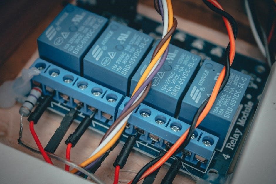
The visual representation of the AUX switch circuit in the Next Gen Ranger wiring diagram provides a clear and organized layout of the electrical connections. It uses symbols and color-coded lines to depict the flow of power from the battery through the switches, relays, and fuses to various accessories. This graphical layout helps users quickly identify the components involved in each circuit, such as AUX 1 through AUX 6, and understand how they are interconnected. The diagram also highlights the locations of key components like the fuse and relay boxes, making it easier to trace and troubleshoot wiring paths. This visual guide is indispensable for both novice and experienced installers, ensuring accurate and efficient setups for custom accessories.
Wire Color Coding and Size Specifications
The Next Gen Ranger AUX switches wiring diagram provides detailed information on wire color coding and size specifications, ensuring accurate connections. Each circuit is color-coded for easy identification, with wires such as red, yellow, and black representing specific functions. The diagram specifies wire gauges, typically ranging from 16 AWG to 20 AWG, depending on the accessory’s power requirements. This information is crucial for maintaining proper electrical flow and preventing damage to components. By adhering to these specifications, users can ensure safe and reliable installations. The clear labeling of wire colors and sizes simplifies the process of connecting switches to accessories, reducing the risk of errors during DIY projects.
Locations of Fuse and Relay Boxes
The Next Gen Ranger AUX switches wiring diagram PDF details the locations of fuse and relay boxes, essential for proper electrical system management. The primary fuse box is located under the hood on the driver’s side, while an additional fuse box is found inside the cabin on the passenger side. The auxiliary fuse and relay box is positioned near the battery on the driver’s side of the engine bay. These locations are critical for diagnosing issues, replacing fuses, and ensuring the AUX switches operate correctly. The diagram provides precise information to help users identify and access these components efficiently, making installations and repairs more straightforward. Accurate knowledge of these locations is vital for maintaining the electrical integrity of the vehicle.
DIY Installation Guide
The Next Gen Ranger AUX switches wiring diagram provides a clear, step-by-step guide for installing and customizing auxiliary switches. Perfect for DIY enthusiasts, it ensures a seamless upgrade experience.
Essential Tools and Materials Needed

To successfully install and customize your Next Gen Ranger AUX switches, gather essential tools and materials. Start with a multimeter for voltage testing, wire cutters, and strippers for precise connections. A soldering iron and heat shrink tubing ensure durable joints. Torx and Phillips screwdrivers are necessary for accessing panels. A wiring diagram PDF is crucial for guidance. Use high-quality wires, connectors, and fuses to maintain reliability. Protective gear like gloves and safety glasses is a must. Ensure all components meet Ford specifications to avoid compatibility issues. Having a well-organized toolkit and materials ready will streamline the process and minimize potential errors during installation.
Step-by-Step Instructions for AUX Switch Wiring
Begin by consulting the Next Gen Ranger AUX switches wiring diagram to understand the circuit layout. Disconnect the battery to ensure safety. Access the auxiliary switch panel, typically located in the instrument cluster or overhead console. Identify the corresponding fuse and relay box, usually found in the engine bay. Use a multimeter to verify power supply to the switches. Carefully strip and connect wires to the appropriate terminals, following the diagram’s color coding. Secure all connections with heat shrink tubing or electrical tape. Reconnect the battery and test each switch to ensure proper functionality. If adding accessories, route wires neatly and avoid interference with other components. Double-check all connections for reliability and safety before finalizing the installation.
Connecting Accessories to AUX Switches
To connect accessories to the AUX switches, start by identifying the corresponding wire for each switch using the wiring diagram. Locate the blunt-cut wires near the auxiliary fuse and relay box in the engine bay. Match the wire color and size to your accessory, ensuring compatibility. Use appropriate connectors or splice safely into the wiring harness. For high-power accessories like winches or lights, verify the wire gauge matches the load requirements. Connect the positive wire to the switch’s output terminal and the negative to ground. Test the accessory operation to confirm proper functionality. Ensure all connections are secure and insulated to prevent short circuits. Refer to the diagram for specific routing and avoid overloading circuits to maintain system reliability.
Troubleshooting Common Issues
Identify power supply issues by checking fuses and relays. Inspect wiring for short circuits or damage. Consult the wiring diagram for guidance. Ensure switches operate correctly and connections are secure.
Identifying and Solving Power Supply Problems
Power supply issues can often be traced to faulty fuses or relays. Start by inspecting the fuse box and relay module for blown fuses or tripped circuits. Consult the wiring diagram to locate the correct fuse or relay associated with the malfunctioning accessory. Use a multimeter to test for power at the switch and verify if voltage is present. If no power is detected, check the wiring connections for damage or corrosion. Ensure all connections are secure and free from debris. Refer to the wiring diagram for specific wire color coding and sizes to confirm proper connections. If issues persist, test the relay by swapping it with a known working one. Always follow safety guidelines when working with electrical systems to avoid further damage or risk of injury.
Fixing Faulty Switches and Fuses
If a switch or fuse is malfunctioning, start by identifying the faulty component using the wiring diagram. Test the switch for continuity with a multimeter. If it fails, replace it with an identical switch. For fuses, locate the appropriate fuse box (near the battery or under the hood) and test the suspect fuse for continuity. Replace blown fuses with one of the correct amperage rating; Ensure all connections are clean and secure, as corrosion can cause intermittent issues. Refer to the wiring diagram to trace connections and verify proper wiring. If a relay is suspect, swap it with a known working one to confirm functionality. Always follow safety precautions when handling electrical components to avoid damage or injury.
Best Practices for Maintenance and Repair
Regularly inspect the auxiliary switch system to ensure all connections are clean and secure. Use the wiring diagram to trace circuits and verify proper wiring. Test switches and fuses with a multimeter to identify faults before replacing components. Avoid cutting or splicing wires, as this can lead to electrical issues. Always disconnect the battery before performing repairs to prevent accidental short circuits. Consult the owner’s manual or a certified technician for complex repairs. Keep the wiring diagram handy for quick reference during maintenance. Ensure all replaced fuses or switches match the original specifications. By following these practices, you can maintain system reliability and ensure safe, efficient operation of your Next Gen Ranger’s auxiliary switches.